Camera: Orbit#
This tutorial example uses an earth globe created from a sphere source with texture mapping applied as described here. You might just as well load a global 2D data set and check Spherical Coordinates to obtain a globe representation that the camera can orbit.
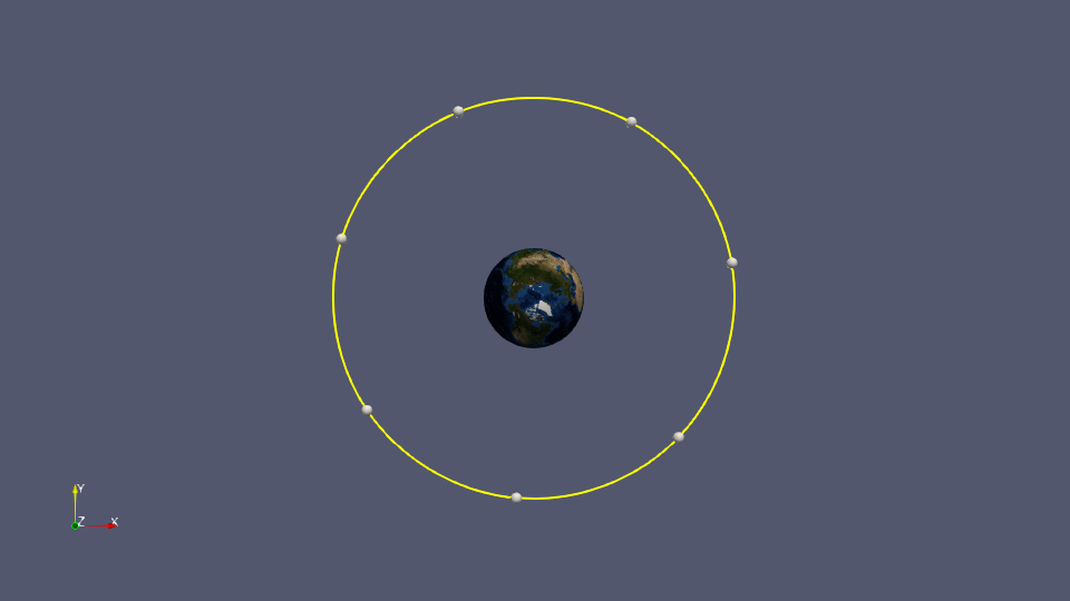
Figure 1: Top view of Camera Orbit track consisting of 7 keyframes
Once you have loaded your earth globe you are ready to set up the start view of the globe. This is the camera perspective from which the orbit will start. Please make sure that the visibility of your data module in the Pipeline Browser is switched on and that you have selected the data module around which the camera shall orbit.
In case you consider saving an animation of the camera orbit to disk, we encourage you to lock the RenderView to a custom size up front. Be sure to use the same aspect ratio as for the resolution of the final output images. See the how-to on Animations & screenshots for details.
Example 1: Upright axis of rotation#
Set up the start view
How about starting the orbit with a view of Europe and Africa? The steps are as follows:
Click on the +Y button (Set view direction to +Y) in the menu bar
Zoom in as much as you like using the right mouse button
Click on the Adjust Camera button in the toolbar at the top of the RenderView
In the Adjust Camera dialogue window (see fig. 2), Camera Parameters section, set:
Position: x value – y value – 0
Focal Point: 0 – 0 – 0
View up: 0 – 0 – 1
View angle: 30.00
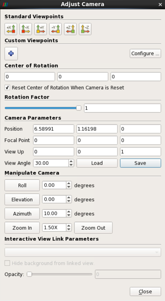
Figure 2: Adjusting the camera for a view of Europe and Africa
In the Manipulate Camera section of the window:
Set Azimuth to a value of, e.g., 10.00degrees (values from -360 to 360 degrees are accepted)
Press the Azimuth button repeatedly to rotate the camera to a view of Europe & Africa (see figure 3)
Use the Save button to save the current camera settings as a .pvcc file
Click on Close
Set up the animation
For the following example, let us assume that you have time-varying global data that you would like to see displayed on the Earth globe in an animation. The data consist of 250 time steps and you would like to see the Earth rotate once during the time animation. When the final time step has been reached, planet Earth shall rotate once more; this will allow the viewer to examine the global distribution of the variable at the last time step. If your data changed gradually over time, you would consider at least a 20 seconds animation for the 2 rotations. With 25 frames per second for smooth animation playback, the 250 time steps would be played back as 250 frames in the first 10 seconds.You would then add another 250 frames for the second rotation of planet Earth at time step 250, yielding 500 frames in total for this animation.
For the sake of simplicity, we show only the earth background without additional data in this first visualization example. For details on combining time-varying data and camera movements, see the how-to on Camera: Interpolate camera locations.
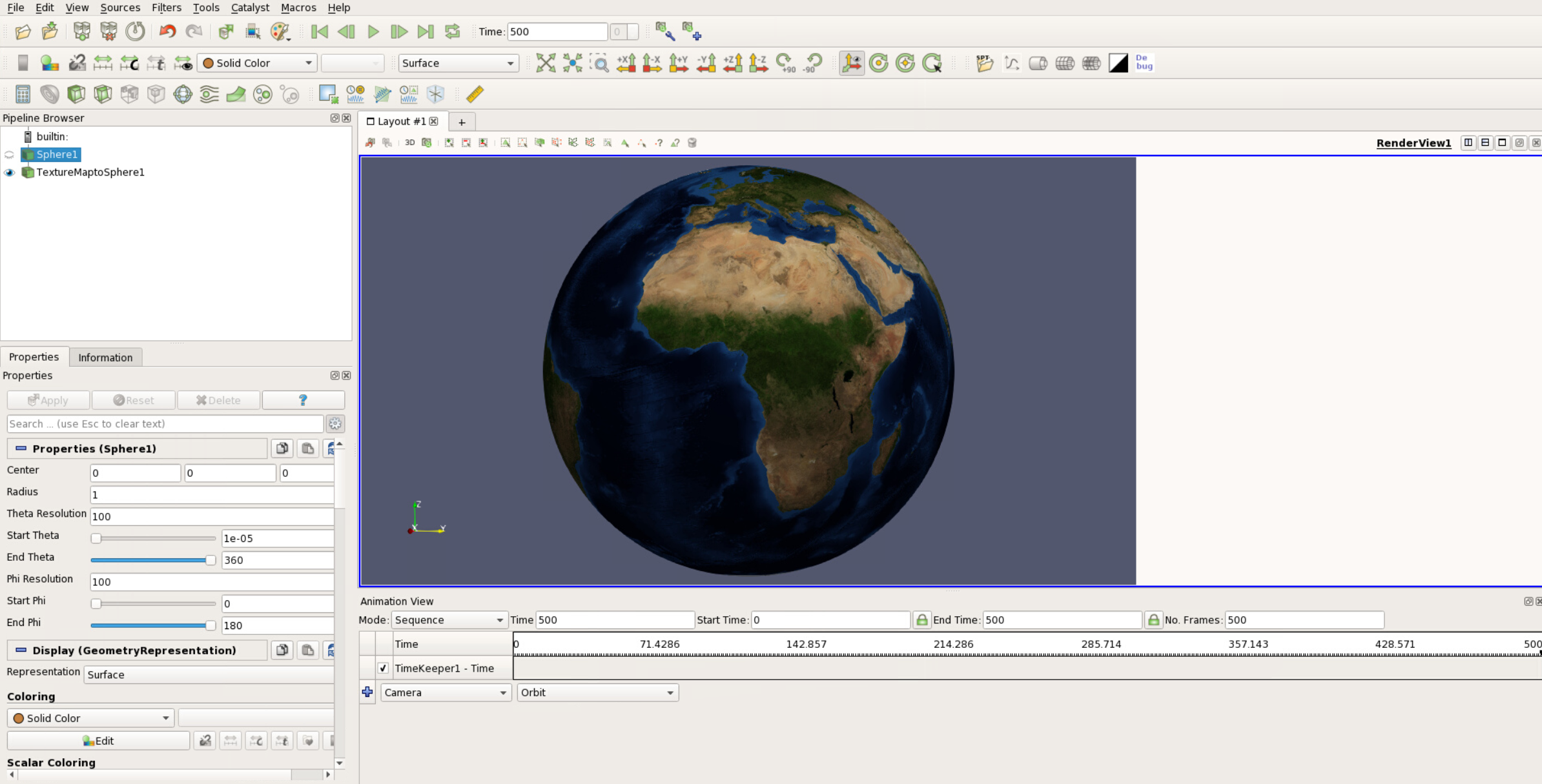
Figure 3: Defining the sequence in the Animation View
In the Animation View that you reach via the View menu item, do the following:
Set Mode to Sequence and adjust the time settings to those in figure 3
Select Camera and Orbit and click on the blue plus symbol
In the dialogue window Create Orbit (see figure 4), keep the default and click OK.
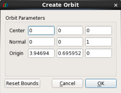
Figure 4: Parameters for creating a Camera Orbit
This has added a Camera track to your Animation View. If you click on the green Play button in the main menu bar, your globe will start rotating nicely – however, the rotation is clockwise, the exact opposite of what we need for Earth. Moreover, the globe rotates only once. To fix this:
Double-click on the Camera track
In the Animation Keyframes dialogue window, double-click on Path…(see figure 5)
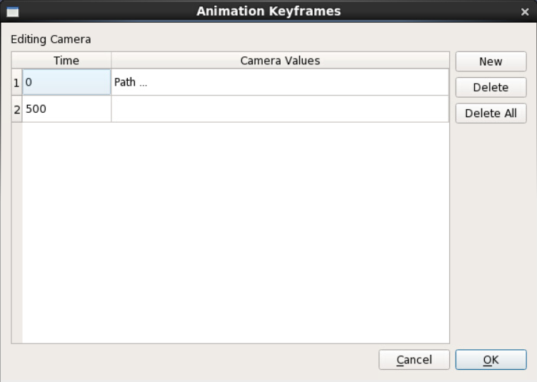
Figure 5: Animation Keyframes dialogue
In the Keyframe Interpolation dialogue window, select the option Camera Position on the top left.
This will bring up the Spline Parameters or x, y, z values of the Position Control Points as shown in figure 6.
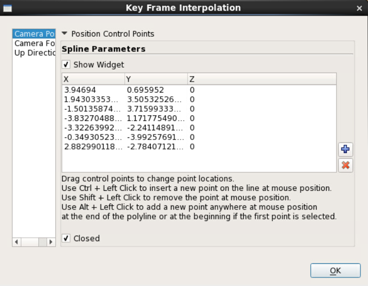
Figure 6: Coordinates of position control points
With Show Widget and Closed enabled, the RenderView now shows the Camera Orbit as a yellow circular track with 7 control points (see figure 1).
General info: Modifying the Orbit in the Render View using the mouse
This section explains how to modify the originally circular Camera Orbit track using the mouse. Doing this is not necessary for the two animation examples presented here, but it might come in handy for future visualization projects of yours. The controls are as follows:
Selecting & shifting a control point:
move the cursor onto one of the white control points
press the left mouse button once until the point turns red (see figure 7)
with the left mouse button pressed, move the mouse to shift the control point (see figure 8)
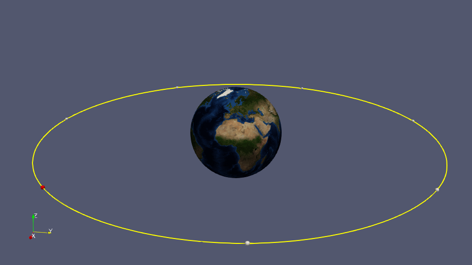
Figure 7: Camera Orbit track with control point selected
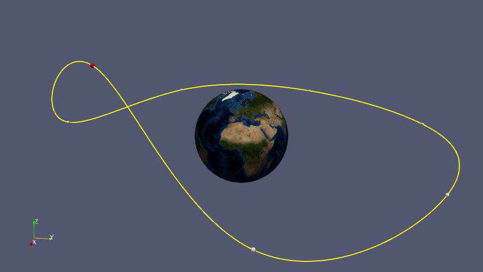
Figure 8: Camera Orbit track with control point shifted
Deleting a control point:
move the cursor onto the control point
delete the point by holding down the shift button and a left mouse button click
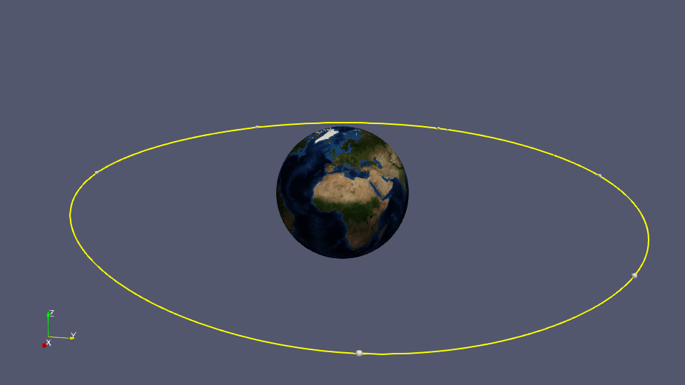 Figure 9: Camera Orbit track after deletion of one control point
Shifting the Orbit track in 3D space:
move the cursor onto the yellow Orbit track
press the left mouse button - note how the Orbit track turns white
with the left button pressed, move the mouse to shift the Orbit track
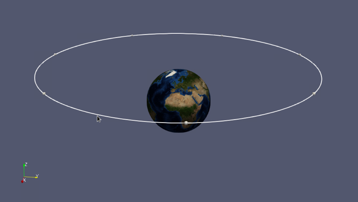
Figure 10: Shifted Camera Orbit track
Modifying the Orbit track radius:**
move the cursor onto the yellow Orbit track
press the right mouse button - note how the Orbit track turns white
with the right button pressed, move the mouse forward and backward to decrease or increase the radius of the Orbit track
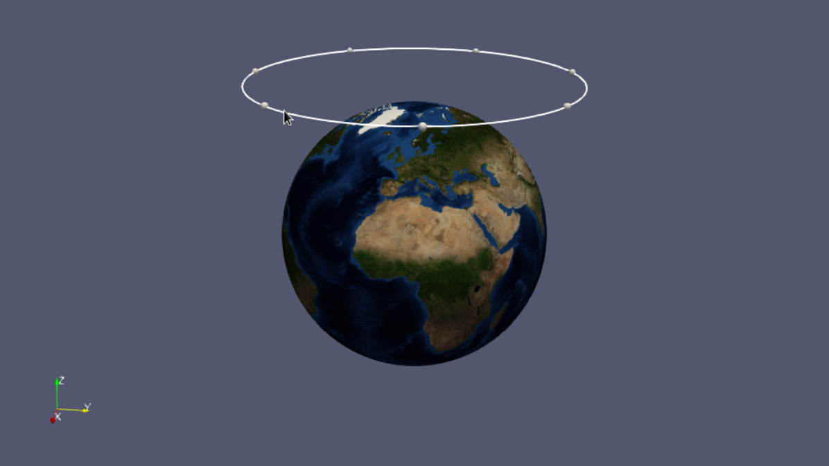
Figure 11: Camera Orbit track with decreased radius
Modifying the Orbit for two rotations
To modify the circular Camera Orbit as desired for example 1, we will start from the default Camera Orbit that was created when you added the respective track to the Animation View. In case you have meanwhile changed the Orbit Track you can create a fresh one by:
deleting the Camera Orbit track in the Animation View
resetting the view using the Adjust Camera button and Load to load your .pvcc file
adding a fresh Camera Orbit track to the Animation View as described above
When you are ready, open the Key Frame Interpolation window andCamera Position option shown in figure 6. To set up two turns of the camera in reverse direction of rotation you need to change the x, y, z values of the control points manually. the first step is reversing their order and the second step is duplicating the entries. To avoid confusion we suggest the following:
Copy all entries to a text editor of your choice
Make the necessary modifications
Create the respective control points in the Key Frame Interpolation dialogue
Compare your Key Frame Interpolation dialogue with the modified Position Control Points in figure 7.
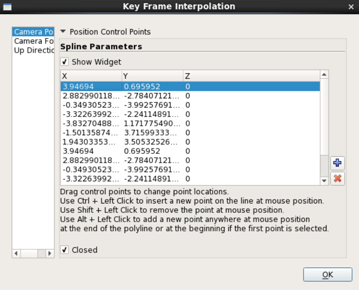
Figure 12: Modified position control points for two rotations with reversed direction
Next:
Click 2x OK
Click the Play button to test the Camera Orbit
Looks good? Then you’re ready to either load your own data for display in spherical projection or to save an animation as described here.
Video 1: Earth globe performing two rotations
Remember to save your ParaView project as a state file.
Example 2: Rotation around tilted z-axis#
If you are interested in a specific region of the Earth, e.g. the polar regions, you will likely want to use a camera perspective focusing on this area. In this example you will learn how to let the Earth globe rotate at an angle. The example has 2 parts: In part a), the globe is centered and fully visible. In part b) only the upper part of the globe is shown.
For this example we have added a 2D slice of data to the globe: The magnitude of the horizontal sea ice velocity from the ICON Ocean dataset icon_ocean.nccontained in the ParaView workshop folder on Mistral: /work/kv0653/ParaView-Workshop/ICON/icon_ocean.nc To see the sea ice velocity data displayed on top of the globe, the radius of the sphere source needs to be increased, e.g. from a value of 1 to 193. Once you’ve done this, repeat the steps for setting up the start view outlined above and compare your RenderView to figure 13.
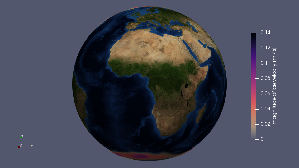
Figure 13: Upright Earth globe with magnitude of ice velocity displayed
Note that the camera parameters have changed with the increased Earth radius (see figure 14) and that it is therefore advisable to save the new camera start view as a .pvcc file.
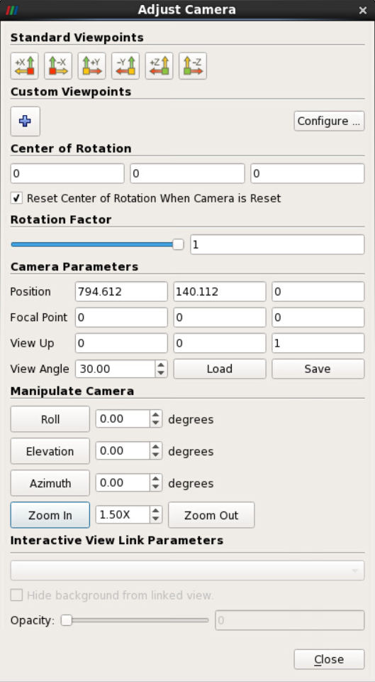
Figure 14: Adjust Camera dialogue for Earth with sphere radius 193
a) Centered globe with tilted axis#
In this example we simply tilt the Earth globe and reset the up direction; the Earth remains centered in the render view. Use your mouse to modify the camera in such a way that you get a good view of the Arctic (see figure 15). Notice how the Adjust Camera properties (see figure 16) have changed compared to the upright position (see figure 13).
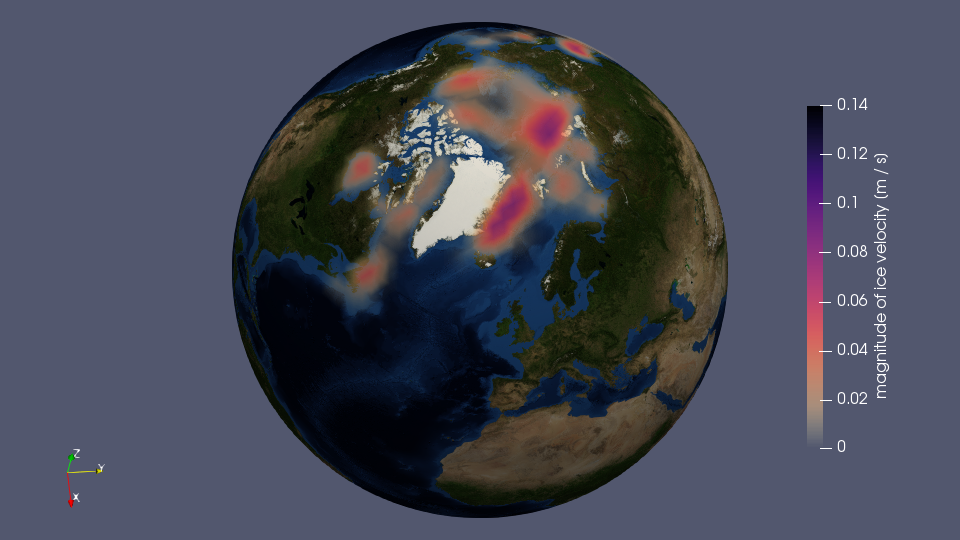
Figure 15: Tilted Earth globe with ice velocity magnitude displayed
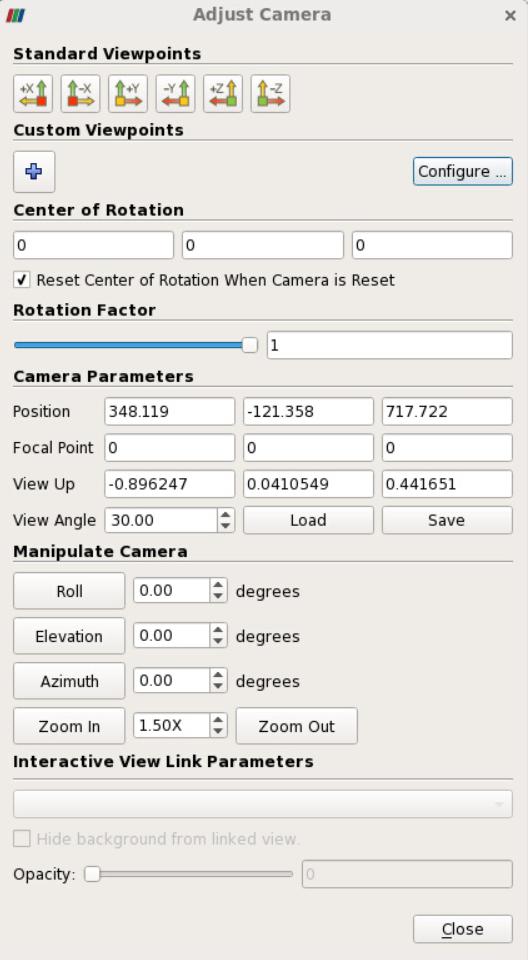
Figure 16: Adjust Camera dialogue for tilted Earth
The z-coordinate of the position is now non-zero and the entries of View Up have changed. What you need to do now is reset View Up to 0 - 0 - 1 while keeping the other entries as they are (see figure 17). The result is shown in figure 18: Comparing this one to figure 15, you will notice that the z-axis arrow of the orientation axes is now aligned vertically.
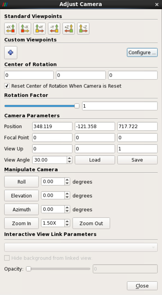
Figure 17: Adjust Camera dialogue for tilted Earth with View Up set to 0 - 0 - 1
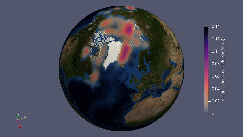
Figure 18: Tilted Earth globe with View Up set to 0 - 0 - 1
Delete any previously existing Camera track in the Animation View and create a new one using the blue plus symbol and the option Camera Orbit. Make sure that the Mode is set toSequence. In the Create Orbit dialogue window, the settings should be as follows (see figure 19):
Center: 0 - 0 - 0
Normal: 0 - 0 - 1
Origin: xcoord - ycoord - zcoord (as per Adjust Camera - Position coordinates)
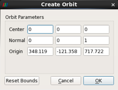
Figure 19: Parameters for creating the tilted Camera Orbit
Press the Play button to see the Earth rotate while the camera focuses on the Arctic region.
Video 2: Earth globe with ice velocity magnitude rotating at an angle
Remember to save your ParaView project as a state file.
b) Upper part of the globe#
We suggest that you continue from the previous example, with your Render View looking similar to figure 18. Our next goal is to achieve a view similar to figure 20.
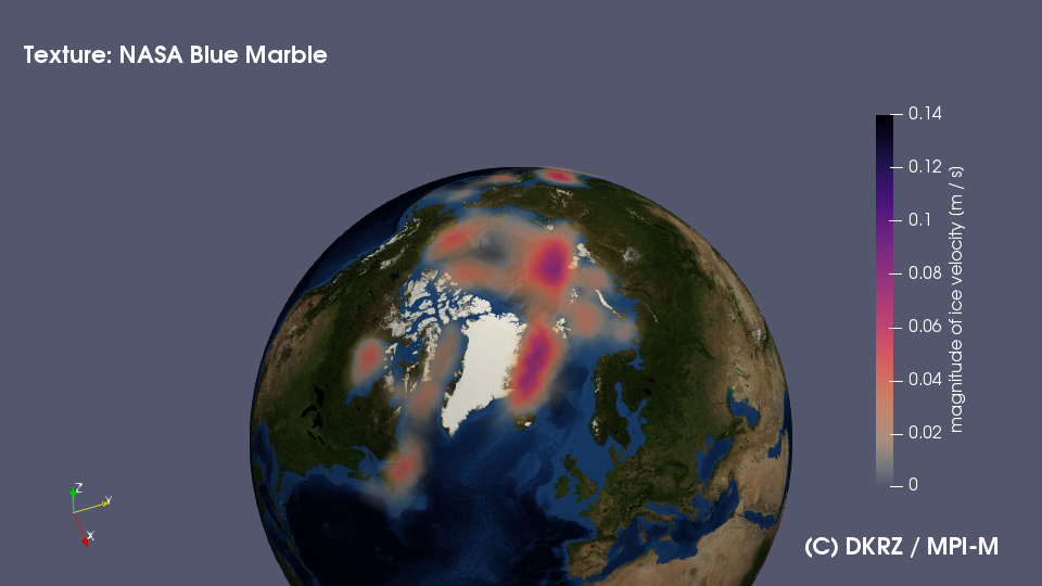
Figure 20: Tilted and vertically shifted Earth globe with ice velocity magnitude displayed
This can be accomplished by:
Deleting the previous Camera Orbit track
Adjust Camera: Center of Rotation 0 - 0 - 180; then Close
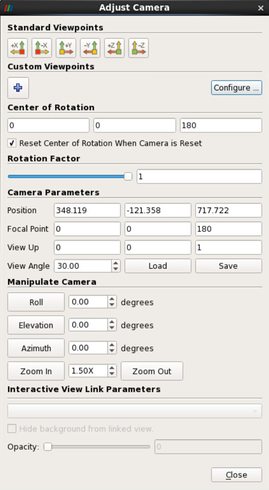
Figure 21: Adjust Camera dialogue for tilted Earth with focal point and center of rotation set to 0 - 0 - 180
Add Camera: Orbit to Animation View
Create Orbit: Orbit Parameters -> Center: 0 - 0 - 180; Normal: 0 - 0 - 1; Origin: x - y - z values as before
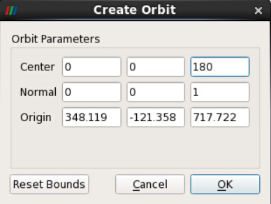
Figure 22: Parameters for creating the tilted and vertically shifted Camera Orbit
Click OK
Press Play button in the Animation Controls
Please note that this will only shift the Earth globe (or rather the Camera) vertically in the Render View.
Video 3:Earth globe with ice velocity magnitude rotating at an angle and shifted vertically in the Render View
Remember to save your ParaView project as a state file.